Concept of heating pipeline: All pipes that transport steam or hot water are called heating pipelines. The task of heating pipelines: transport the heat energy produced by boilers to indoor heating equipment through heat media such as steam and hot water to meet the needs of production and life.
1. Classification of heating pipelines
According to the different media flowing in the pipes, they can be divided into steam and hot water pipelines. According to their working pressures, they can be divided into three types: low-pressure, medium-pressure and high-pressure pipelines. According to their laying locations, they can be divided into indoor and outdoor heating pipelines.
2. Characteristics of heating pipelines
The most prominent feature of hot water and steam pipelines is the thermal expansion and contraction of the pipelines caused by temperature changes. The temperature of the pipeline is room temperature during installation. During the initial operation (transporting heat medium), the pipeline will stretch sharply due to the sudden increase in temperature. When the operation stops, the pipeline will gradually shrink back as the temperature drops. When the pipeline expands and contracts, it will produce a large push (pull) stress at both ends of the fixed points, causing the pipeline to deform or even damage the bracket. Therefore, measures should be taken (compensators) when installing the heating pipeline to eliminate the push and pull stress caused by temperature changes. For steam pipelines, in addition to thermal expansion and contraction, there is another feature: condensate will be generated during the transportation of steam due to heat dissipation and other reasons. Condensate in the steam pipeline is extremely detrimental to the normal operation of the system. It not only deteriorates the quality of steam, but also hinders the normal circulation of steam, generating water hammer and noise. Therefore, measures should be taken when installing the steam pipeline (devices for draining and removing condensate) to discharge the condensate in time.
Material properties
For heating pipelines that are subjected to both medium temperature and pressure, the requirements of working conditions must be met in terms of heat resistance and mechanical properties. The mechanical properties of steel are related to temperature, but not to time. At a certain working temperature, its yield strength, tensile strength and allowable stress can be considered as constant values within the service life. The mechanical properties of plastic materials are related to both temperature and time. Under high temperature, its mechanical strength gradually decreases, resulting in creep (under constant stress, the material continues to produce plastic deformation), relaxation (compression force reduces by itself) and high-temperature oxidation (oxidative damage occurs at high temperature). Therefore, when designing plastic pipes, the mechanical properties at the end of the design service life must be considered.
Determination of use conditions
The use conditions are the time-temperature distribution of the pipeline. The mechanical properties of plastic materials are related to temperature and time, and the use conditions determine the value of the design stress. Therefore, before determining the wall thickness of the pipeline, the use conditions must be determined first. According to the heating system regulation curve, the whole year is divided into several stages, and the highest medium temperature in each time period is listed to obtain the time-temperature distribution of the pipeline. Some standards set several typical systems to give time-temperature distribution according to the application field, which is called the use condition level. If the designed pipeline operation law is close to a certain use condition level, the corresponding S value can be directly selected.
The relevant terms in the common use condition level table are explained as follows:
a. Design temperature
In the use condition level table, the design temperature is defined as the design value of the water delivery system. According to the custom of the heating industry, this temperature is the operating temperature on the operation adjustment curve, and its maximum value is the design water supply temperature commonly used in the heating industry.
b. Maximum design temperature.
In the use condition level table, the maximum design temperature is defined as the highest value of the design temperature that only appears for a short period of time. In the heating system, the design water supply temperature commonly used in the heating industry is the highest operating temperature, and there is no maximum design temperature; in the domestic hot water system, the maximum design temperature can be understood as the value of the water supply temperature higher than the system design temperature when the flow rate changes.
c. Fault temperature.
In the use condition level table, the fault temperature is defined as the highest temperature that may exceed the control limit when the control system is abnormal.
d. Use time of XX temperature.
The time unit is years or hours, and the total use time corresponding to various temperatures within the 50-year design service life of the pipeline. This time includes heating time and non-heating time. In the use condition level table, the use time of design temperature, maximum design temperature and fault temperature adds up to 50 years.
Ⅰ. Layout of outdoor heating pipelines
The layout of outdoor heating pipelines should be as economical as possible while ensuring the safe and reliable operation of the heating pipelines. The layout forms are divided into tree planting and ring. The ring avoids the disadvantages of the tree branch, but the investment is large and it is generally less used. Advantages of the tree branch: low cost and convenient operation and management. Disadvantages of the tree branch: when a local failure occurs, the heating of subsequent users is stopped. Applicable: occasions where the requirements for heating supply are not strict.
Ⅱ. The laying form of outdoor heating pipelines
It is divided into two laying forms: ground (overhead) and underground.
(I) Overhead laying on the ground
Overhead laying on the ground is to install the pipeline on an independent bracket on the ground or on the bracket of the wall or column. Advantages: not affected by the groundwater level, the earthwork is minimal during construction, and it is easy to maintain. Disadvantages: large footprint, large heat loss, easy damage to the insulation layer, affecting the appearance. According to the height of the bracket, it can be divided into three laying forms: low, medium and high brackets.
(1) Low support laying: This laying method requires a clear distance of 0.5~1m between the bottom of the pipe (the bottom of the insulation layer) and the ground. As shown in the figure below.
(2) Medium support laying: This laying method is suitable for places where pedestrians and large vehicles pass by, and the clear distance between the bottom of the pipe and the ground is 2.5~4m.
(3) High support laying: This laying method is suitable for traffic arteries or crossing roads and railways. The clear height is 4m when crossing roads and 6m when crossing railways.
(II) Underground laying
Underground laying can be adopted when overhead laying is not allowed in cities due to planning and aesthetic requirements. Underground laying is divided into two types: trench laying and non-trench laying. Trench laying is usually adopted. Trench laying is further divided into three types: passable trench, semi-passable trench and non-passable trench.
(1) Passable trench laying is suitable for the main trunk lines of factory areas, where there are many pipelines (generally more than 6 pipelines) and under the main streets of cities. In order to allow maintenance personnel to walk freely in the trench, the width of the trench walkway is greater than 0.7m and the height is ≥1.8m.
(2) Semi-passable trench laying is suitable for trunk lines with 2~3 pipelines and infrequent maintenance. The height allows maintenance personnel to bend down and walk in the trench. Generally, the clear height is 1.4m and the clear width of the passage is 0.6~0.7m.
(3) Non-passable trench laying is suitable for branch lines that do not require frequent maintenance and have less than two pipelines. The distance between the outer skin of the insulation layer of the two pipes is greater than 100mm, the outer skin of the insulation layer is 120mm from the bottom of the trench, and greater than 100mm from the trench wall and the lower edge of the trench cover.
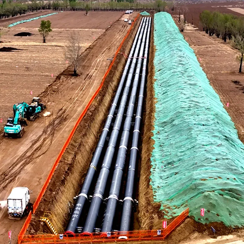
(4) Trenchless laying Trenchless laying is to bury ordinary pipelines directly in the underground soil layer. It has large heat loss and is difficult to waterproof. In the past, except for the steam heating pipe of the crude oil pipeline, trenchless laying was not used. With the development of outdoor direct burial insulation technology, trenchless laying is becoming more and more widely used. Determine which type of laying the following situations belong to.
Drainage and exhaust devices for outdoor heating pipes
I. Drainage and exhaust devices for steam heating pipes
(I) Drainage and drainage devices for steam pipes
In order to ensure the normal operation of the pipes and remove the condensate in the pipes in time, steam pipes should be equipped with drainage and startup drainage devices.
1. Drainage device for steam pipes
When the steam pipes are operating normally, the steam will produce condensate due to the continuous heat dissipation (heat loss) along the way during transportation. The condensate in the steam main pipe is led to the condensate main pipe through the drain; then it is sent back to the condensate tank in the boiler room along its main pipe. The steam pipe drainage device should be installed at the following locations:
(1) Each low point of the steam pipe;
(2) Before the vertically rising pipe section;
(3) One is installed every 50m in the horizontal pipe;
(4) The pipe blockage where condensate may condense.
2. Startup of steam pipes
Drainage device When the steam pipe system is initially transporting steam (startup), a large amount of (dirty) condensate will be produced due to the high temperature of the steam and the low temperature of the pipe. It is not enough to rely on the steam trap to drain. A separate startup drainage device must be set up to lead the water discharged during startup to the sump, and then flow or pump it to the sewer. The startup drainage device of the steam pipeline should be set at the following locations:
(1) The lowest point where water may accumulate during startup;
(2) Before the pipe bend or vertical rise section;
(3) On the horizontal pipeline, one is set every 100~150m;
(4) On the horizontal pipeline, in front of the flow measurement device.
(II) Air exhaust device for steam and condensate pipelines
After the steam pipeline is installed, the pipeline is filled with air. When the pipeline is subjected to water pressure test and startup operation, all the air must be exhausted; there is also air in the condensate pipeline (air is a non-condensable gas), which is easy to form air plugs in the pipeline and hinder the flow of condensate, so the air must be discharged in time.
1. The exhaust device of the steam pipeline is equipped with a manual air vent valve (not used at ordinary times) at the high point of the steam pipeline. When the pipeline system is subjected to a water pressure test (filling water into the pipeline) or running through steam for the first time, the air in the pipeline system is discharged by using this valve.
2. The exhaust device of the condensate pipeline is usually equipped with an automatic air vent valve at the beginning (high point) of the condensate main pipe. If a steam trap without an exhaust valve is used, an air vent valve should also be installed in front of the steam trap so that the air in the condensate pipeline can be discharged in time during the operation of the system.
2. Exhaust and drain device of hot water heating pipeline
The hot water heating pipeline includes two pipelines: water supply and return water.
Drain and exhaust devices should be installed on both the water supply and return water pipelines.
(I) Exhaust device of the supply and return water pipelines
There are two purposes for installing an exhaust device on the supply and return water pipelines: one is to prevent the formation of air plugs due to the accumulation of air during the operation of the system, which hinders the circulation of hot water and generates noise; the other is to use this device to discharge the air in the pipeline when filling water into the pipeline before the pipeline water pressure test. As shown in the figure below. The exhaust device includes an exhaust valve (generally DN15~DN25) and short pipes before and after it. Its position is usually set at the high point of the supply and return water mains and the high point of the pipe section between the sectional valves.
(II) Drain device for supply and return water pipes
The purpose of setting a drain valve on the supply and return water pipes is to use this device to drain all the test water after the pipeline water pressure test to prevent the pipeline from freezing in winter; second, when the system is shut down for maintenance, this device is required to drain the water in the maintenance section. The drain device includes a drain valve and short pipes before and after it. The diameter of the drain valve and its short pipe is 1/10 of the diameter of the supply and return water pipes and is not less than DN20. It is usually set at the low point of the supply and return water mains and the low point of the pipe section between the sectional valves.
Installation of heating pipes in outdoor trenches
Ⅰ. Installation scope
The installation scope of heating pipes in outdoor trenches generally refers to the outer wall of the boiler room to the outer wall of the user or the heat inlet in engineering. The engineering cost is based on the first valve well outside the building or 1.5m from the outer wall of the building as the dividing point.
Ⅱ. Selection of pipes and valves during installation
Generally, outdoor steam pipes should use ordinary seamless steel pipes, and condensate and supply and return hot water pipes generally use threaded steel pipes (spiral seam electric welded steel pipes, spiral steel pipes). Pipeline bends use simmering or stamping elbows, and reducers use stamping reducers. Valves usually use flanged stop valves and one-way valves. Pipes are connected by welding and flanges. Small-diameter pipes connected to steam traps, exhaust valves, and drain valves can generally use black iron pipes, finished pipe fittings, threads or welding connections. Exhaust valves and drain valves are threaded stop valves.
Ⅲ. Pipeline installation
(I) Bracket installation
1.Types of brackets
The bracket consists of two parts: the support structure and the holding structure. The support structure is usually cantilever or beam type (angle steel or channel steel). The holding structure is called a support (seat), and the bracket is divided into three types: movable bracket, guide bracket and fixed bracket. Movable bracket: used in places where the pipeline can be displaced longitudinally and transversely. Fixed bracket: used in places where the pipeline can withstand the push and pull stress caused by temperature changes and cannot be displaced in any direction. Guide bracket: used in places where only longitudinal displacement of the pipeline is allowed.
2. Installation position of bracket (support)
(1) The installation position of the movable bracket is installed at the first bracket on both sides of the square compensator and the midpoint of its horizontal arm, and the first bracket on both sides of the pipeline bend (elbow).
(2) The installation position of the guide bracket is installed on the straight pipe section between the compensator and the fixed bracket.
(3) The installation position of the fixed bracket is installed between the two compensators, the heat source outlet (near the outer wall), the user entrance (near the outer wall), etc。
3. Installation spacing of bracket (support) (as shown in the table below)
4. Installation of bracket (support)
The bracket should be made, rust-proofed, and anti-corrosive before installation.
(1) The support structure of the bracket (seat) is generally made of angle steel or channel steel, and the bracket is welded with steel plate.
(2) Rust removal of brackets (seats) There are manual, mechanical, pickling and sandblasting methods. Among them, sandblasting has high efficiency and good quality. However, a dust removal device must be installed. Otherwise, a large amount of dust will be generated during the sandblasting process, polluting the environment and harming human health.
(3) The anti-corrosion of brackets (seats) is usually painted with two coats of primer and topcoat. The primer is camphor (red) anti-rust paint or iron red anti-rust paint, and the topcoat is blended paint.
(4) Installation of brackets (seats) The installation of heating pipe brackets (seats) in trenches is carried out in two times: the first time is when the trench wall is built, the supporting structure (angle steel or channel steel) is pre-buried; the second time is when the supporting structure (support seat) is installed when the pipeline is laid.
(II) Laying pipelines
1. Inspection of pipes
The name, specification and material of the pipes should meet the design requirements; there should be no defects such as cracks, heavy skin and severe rust.
2. Rust removal of pipes is usually done by sandblasting. The rust on the outer surface of the pipe is removed to expose the metallic glossy surface.
3. Anti-corrosion of pipes is usually done by spraying the outer surface of the pipe with anti-rust primer twice before laying the pipe. In order not to affect the quality of the weld, leave about 50mm at both ends of each pipe section without painting.
4. Assembly and welding of pipe sections Assembly and welding of pipe sections of appropriate length are done on the flat ground beside the pipe trench. The welding procedure of pipes is as follows: beveling, butting, spot welding and welding.
5. Laying pipes and installing supports
(1) Laying pipes
Put the assembled and welded pipe sections mechanically or manually from the edge of the pipe trench into the brackets in the trench, and connect the pipe sections into a whole pipeline. Then place the pipes and adjust the spacing, slope and slope direction.
(2) Installing supports
When installing fixed supports, the supports, pipes and brackets should be welded firmly. When installing the movable and guide supports, it should be considered that the center line of the support and the center line of the support should not have a large deviation after the thermal expansion of the pipeline. Therefore, the movable supports on both sides of the compensator and the guide supports on the straight pipe section should be installed eccentrically. The eccentric direction is based on the center point of the square compensator, that is, the support on the left side of the compensator deviates to the left side of the center line of its support; the support on the right side of the compensator deviates to the right side of the center line of its support, and the eccentric distance is 1/2 of the thermal expansion of the pipe section between the support and the fixed support (usually 50mm). The movable and guide supports are welded to the pipeline; the guide plate of the guide support is welded to the support.
(III) Compensator machine installation
1.The role of the compensator
The compensator is also called an expansion joint. Its role is to absorb the length of the pipeline extended due to thermal expansion; compensate for the length retracted due to cold contraction.
2. Types of compensators
Compensators are divided into natural and artificial compensators. Natural compensators are natural bends in heating pipes, which are divided into Z-shaped and L-shaped; artificial compensators are square and sleeve compensators. Heating pipes usually use square compensators. The advantage of the square compensator is that it is safe and reliable when the pipeline system is running, and it does not need maintenance at ordinary times. The disadvantage is that it occupies a large area.
3. Making of square compensators
When making square compensators, try to use one pipe to make them. If 2~3 pipes are used, the interface (weld) should be set at the midpoint of the vertical arm. The material of the pipe should be better than or the same as the material of the corresponding pipeline; the wall thickness of the pipe should be thicker than the wall thickness of the corresponding pipeline. When assembling, it should be done on the platform, and the four elbows are all 90° and on the same plane.
4. Installation of square compensators
Under normal circumstances, not all pipe sections of the heating pipeline need to be installed with square compensators from beginning to end. In actual projects, some pipe sections need to be installed with square compensators; some pipe sections do not need to be installed with square compensators. When there is a natural bend in the heating pipeline (that is, there are Z-shaped and L-shaped natural compensators), the straight pipe sections before and after the elbow are short, and square compensators may not be installed. When there is no natural bend in the heating pipe, a square compensator should be installed; or if there is a natural bend, but the straight pipe sections before and after the elbow are long, a square compensator should also be installed on the straight pipe section. The square compensator should be installed at the midpoint of the straight pipe section between the two fixed brackets, and placed horizontally during installation, with the same slope and slope direction as the corresponding pipe. In order to reduce the bending stress of the compensator in the hot state (during operation) and improve its compensation capacity, the square compensator should be pre-stretched or pre-supported when installed (i.e., cold-stretched or cold-supported without heating). The stretching method usually uses a pipe puller and a manual hoist, and a jack can also be used for pre-support.
VI. Pressure test of heating pipes
After the outdoor heating pipe is installed, a pressure test should be carried out to check its strength and tightness.
1. The test medium and test pressure usually use a water pressure test; the test pressure standard is: the strength test pressure value is 1.5 times the working pressure, and the tightness test pressure value is equal to the working pressure.
2. Preparation before pressure test: Install an air vent valve at the high point of the pressure test pipe and a water drain valve at the low point; install plugs and pressure gauges at the beginning and end; connect the water pump.
3. During the pressure test, close the low point water drain valve first. Open the high point air vent valve, fill the pressure test pipe with water until it is full, close the air vent valve after exhausting all the air, and then slowly increase the pressure to the strength test pressure with a hand pump. Observe for 10 minutes. If there is no pressure drop or the pressure drop is within 0.05MPa, reduce it to the working pressure and conduct a comprehensive inspection. The pipe is qualified if there is no seepage or leakage.
V. Insulation of outdoor heating pipe
1.Purpose of insulation:
The purpose of insulation of heating pipes is to reduce the heat loss of heat medium during transportation and to maintain certain parameters (pressure, temperature) of heat medium to meet the requirements of production, life and heating.
2. Commonly used insulation materials
(1) Foam concrete (foam cement) is made of ordinary cement with rosin foaming agent. It is porous and light.
(2) Expanded perlite and its products Perlite is a glassy lava ejected from a volcano. It is transparent and round in shape like pearls, hence its name. It is crushed and roasted at high temperature to form a round powder. It is very light and is usually bonded with cement to form a tile.
(3) Expanded vermiculite and its products Vermiculite is a weathered product of mica. Vermiculite is roasted at high temperature to form layers of small pieces. It is brown and very light. It is bonded with cement to form a tile.
(4) Slag wool Slag wool is made of slag, gray, short fibers, very light and prickly.
(5) Glass wool Glass is melted at high temperature and then sprayed with high-pressure steam to form fibers. It is very light and prickly.
(6) Rock wool is made by roasting rocks at high temperature. It is fibrous and very light.
3. Insulation structure of heating pipes
The insulation structure of heating pipes is shown in the figure. From the inside to the outside are anti-corrosion layer, insulation layer, protective layer and paint (or cold primer). Usually the anti-corrosion layer is two coats of primer (camphor red or iron red anti-rust paint), and no topcoat is applied. The insulation layer is composed of selected insulation materials. The protective layer is divided into two types: asbestos cement and asphalt glass cloth. For exposed heating pipes, in order to indicate the properties of the medium transported in the pipe, color paint is generally applied on the outside of the protective layer. In order to prevent moisture from invading the insulation layer, the heating pipes in the trench are not painted with color paint but with cold primer.
4. Insulation of heating pipes
The insulation construction procedure for heating pipes in trenches is: anti-corrosion layer, insulation layer, protective layer and cold primer.
(1) The pipeline with anti-corrosion layer has been painted with primer twice before laying. This time, the interfaces (welds), elbows and square compensators should be painted with primer twice. If there is any damage to the paint surface of the pipe body during pipe laying, it should also be repainted.
(2) Insulation layer construction
There are five methods for the construction of the insulation layer, including prefabricated tile masonry, wrapping, filling, pouring and manual coating. The most commonly used method is the first method. The prefabricated tile masonry method is to prefabricate the selected insulation material into a tile shape. The number of insulation tiles around the pipe is divided into 2 to 8 pieces according to the size of the pipe diameter. The thickness of the tile is in accordance with the design requirements. The general design thickness is 50, 75, and 100 mm; the length of each tile is about 500 mm. During construction, the prefabricated tiles are laid on the outer surface of the pipe. The longitudinal and transverse joints should be staggered, and asbestos plaster is filled in the joints. The two ends of each tile are tied with iron wire with a diameter of 1 to 2 mm. When the pipe diameter DN ≥ 150 mm, the insulation layer is wrapped with a layer of wire mesh. Expansion joints should be left at the elbows of the pipe, and asbestos ropes should be filled in the joints. The coating method can be used for valves, flanges, etc.
(3) The protective layer is generally an asbestos cement protective layer, and its mass ratio is: 53% 525 cement, 25% expanded perlite powder, 9% grade 4 asbestos, 13% calcium carbonate, and water. The coating thickness is 10~15mm, and the thickness must be consistent, smooth and beautiful, and no bulges should appear on the bottom.
(4) Apply cold primer
Cold primer is to melt asphalt, wait until it cools to below 100℃, add an appropriate amount of gasoline (the mass ratio of asphalt to gasoline is 1.2:2.5) and mix evenly. When painting, the action should be fast and the surface should be uniform and beautiful.
294.webp)
476.webp)
420.webp)
146.webp)
460.webp)
287.webp)
274.webp)

