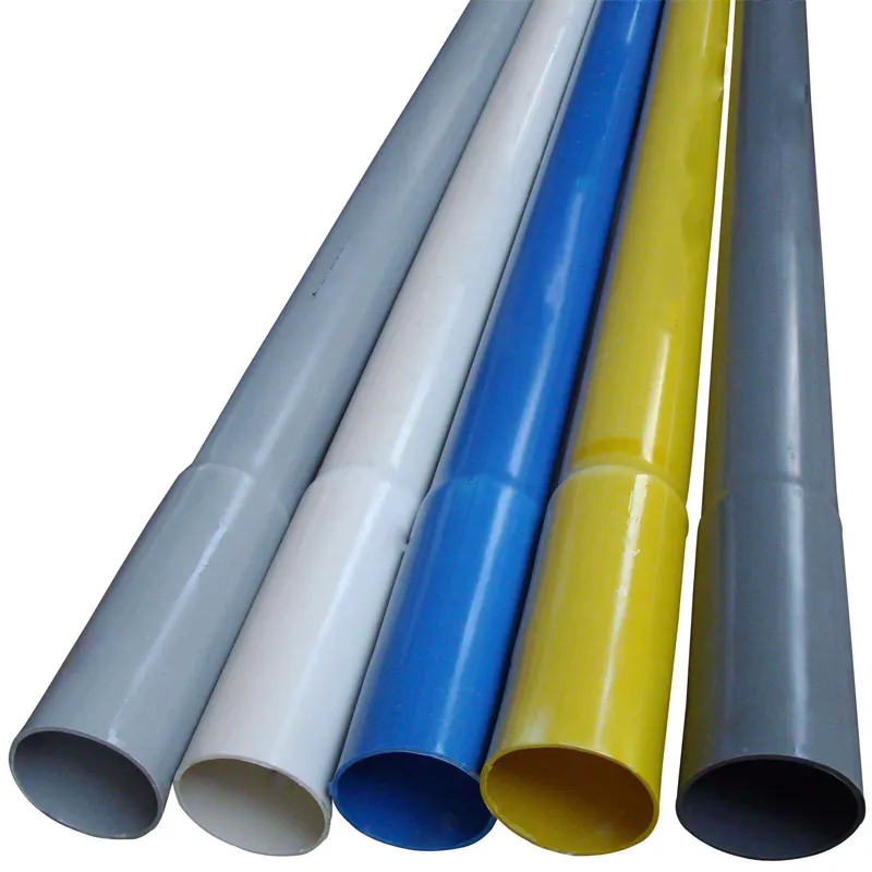
The length of the pipe is 4m or 6m, which can also be determined according to the order requirements.
The colors are blue and white, which can also be determined according to the order requirements.
The color-adjustable protective layer material can be provided according to customer requirements.
PVC-U Water Supply Pipe Specification
| PVC Pipe Straight | S、SDR | NOD(mm) | Wallthickness(mm) | PVC Pipe Straight | S、SDR | NOD(mm) | Wallthickness(mm) |
| PN 0.63MPa | S16 SDR33 | 63 | 2.0 | PN 0.8MPa | S12.5 SDR26 | 50 | 2.0 |
| 75 | 2.3 | 63 | 2.5 | ||||
| 90 | 2.8 | 75 | 2.9 | ||||
| S20 SDR41 | 110 | 2.7 | 90 | 3.5 | |||
| 125 | 3.1 | S16 SDR33 | 110 | 3.4 | |||
| 140 | 3.5 | 125 | 3.9 | ||||
| 160 | 4.0 | 140 | 4.3 | ||||
| 180 | 4.4 | 160 | 4.9 | ||||
| 200 | 4.9 | 180 | 5.5 | ||||
| 225 | 5.5 | 200 | 6.2 | ||||
| 250 | 6.2 | 225 | 6.9 | ||||
| 280 | 6.9 | 250 | 7.7 | ||||
| 315 | 7.7 | 280 | 8.6 | ||||
| 355 | 8.7 | 315 | 9.7 | ||||
| 400 | 9.8 | 355 | 10.9 | ||||
| 450 | 11.0 | 400 | 12.3 | ||||
| 500 | 12.3 | 500 | 15.3 | ||||
| 630 | 15.4 | 630 | 19.3 | ||||
| PN 1.0MPa | S10 SDR21 | 40 | 2.0 | PN 1.25MPa | S8 SDR17 | 32 | 2.0 |
| 50 | 2.4 | 40 | 2.4 | ||||
| 63 | 3.0 | 50 | 3.0 | ||||
| 75 | 3.6 | 63 | 3.8 | ||||
| S12.5 SDR26 | 90 | 4.3 | 75 | 4.5 | |||
| 110 | 4.2 | 90 | 5.4 | ||||
| 125 | 4.8 | S10 SDR21 | 110 | 5.3 | |||
| 140 | 5.4 | 125 | 6.0 | ||||
| 160 | 6.2 | 140 | 6.7 | ||||
| 180 | 6.9 | 160 | 7.7 | ||||
| 200 | 7.7 | 180 | 8.6 | ||||
| 225 | 8.6 | 200 | 9.6 | ||||
| 250 | 9.6 | 225 | 10.8 | ||||
| 280 | 10.7 | 250 | 11.9 | ||||
| 315 | 12.1 | 280 | 13.4 | ||||
| 355 | 13.6 | 315 | 15.0 | ||||
| 400 | 15.3 | 355 | 16.9 | ||||
| 500 | 19.1 | 400 | 19.1 | ||||
| 630 | 24.1 | 500 | 23.9 | ||||
| 630 | 30.0 | ||||||
| PN 1.6MPa | S6.3 SDR13.6 | 25 | 2.0 | PN 2.0MPa | S6.3 SDR13.6 | 25 | 2.0 |
| 32 | 2.4 | 32 | 2.4 | ||||
| 40 | 3.0 | 40 | 3.0 | ||||
| 50 | 3.7 | 50 | 3.7 | ||||
| 63 | 4.7 | 63 | 4.7 | ||||
| 75 | 5.6 | 75 | 5.6 | ||||
| 90 | 6.7 | 90 | 6.7 | ||||
| S8 SDR17 | 110 | 6.6 | S8 SDR17 | 110 | 6.6 | ||
| 125 | 7.4 | 125 | 7.4 | ||||
| 140 | 8.3 | 140 | 8.3 | ||||
| 160 | 9.5 | 160 | 9.5 | ||||
| 180 | 10.7 | 180 | 10.7 | ||||
| 200 | 11.9 | 200 | 11.9 | ||||
| 225 | 13.4 | 225 | 13.4 | ||||
| 250 | 14.8 | 250 | 14.8 | ||||
| 280 | 16.6 | 280 | 16.6 | ||||
| 315 | 18.7 | 315 | 18.7 | ||||
| 355 | 21.1 | 355 | 21.1 | ||||
| 400 | 23.7 | 400 | 23.7 | ||||
| 500 | 29.7 | 500 | 29.7 | ||||
| PN 2.5MPa | S4 SDR9 | 20 | 2.3 | PN 2.5MPa | S5 SDR11 | 110 | 10.0 |
| 25 | 2.8 | 125 | 11.4 | ||||
| 32 | 3.6 | 140 | 12.7 | ||||
| 40 | 4.5 | 160 | 14.6 | ||||
| 50 | 5.6 | 180 | 16.4 | ||||
| 63 | 7.1 | 200 | 18.2 | ||||
| 75 | 8.4 | ||||||
| 90 | 10.1 | ||||||
Construction
1. General regulations
1.1 The horizontal clearance between the pipeline and the adjacent pipeline should not be less than the groove width required for construction and maintenance and the distance required for the installation of auxiliary structures such as valve wells. The horizontal clearance between adjacent pipelines with high water content such as ditches and toxic and harmful gas pipelines such as high-pressure gas transmission should not be less than 1.5m, and drinking water pipelines should not be laid under drainage pipelines and sewage pipelines.
1.2 The horizontal distance between the center line of the pipeline and the outer wall (column) skin of the building (structure) should not be less than the following regulations:
1m when the nominal outer diameter is less than or equal to 200mm;
3.0m when the nominal outer diameter d is greater than 200mm.
1.3 The pipeline foundation should be lower than the bottom elevation of the building (structure) foundation. The pipeline should not be laid within the range affected by the force of the building (structure) foundation. When it is necessary to cross, appropriate protective measures should be taken.
1.4 When the pipeline crosses railways, highways and various types of crossing pipe sections, extension wells should be set up on both sides of the roadbed. The extension pipes should be made of anti-corrosion steel pipes and should comply with the provisions of relevant current standards.
1.5 Pipelines should avoid green belts as much as possible. When crossing is necessary, protective measures should be taken.
1.6 When the pipeline crosses the upper part of other pipelines, the net distance between the bottom of the PVC-U Water Supply Pipe and the top of the lower pipeline should not be less than 0.2m, and the foundation treatment should be carried out in accordance with the design specifications; when there is no design regulation, it can be handled in accordance with the provisions of the "Construction and Acceptance Specifications for Water Supply and Drainage Pipeline Engineering" (GB 50268).
1.7 When there is no design regulation, the pipeline shall not use full concrete for foundation treatment or to enhance the bearing capacity of the pipeline.
1.8 The buried depth of the pipe top in the road should not be less than 1.0m; when the nominal outer dn is greater than 63mm under the sidewalk, it should not be less than 0.75m; when the nominal outer diameter dn is not greater than 63mm, it should not be less than 0.5m. In the permafrost zone, the pipe top depth should be below the frozen layer.
1.9 When using cold mix asphalt for sealing or bonding, the bending radius shall not be less than 300 times the outer diameter of the pipe; when using cold mix asphalt for bonding, the nominal outer diameter dn is less than 160mm.
1.10 The installation slope of the drainage pipe is generally not more than 1°.
1.11 When the PVC-U Water Supply Pipe is bent and diverted, the construction environment should be less than three years of measurement operation, and the outer wall of the supporting pipe should be filled before construction.
1.12 When closing, entering the room, joints, supporting cross blocks and accessories of the load-bearing components, all related facilities should be paid attention to.
146.webp)
598.webp)
904.webp)
211.webp)
370.webp)
339.webp)


328.webp)
294.webp)
476.webp)

