Pipeline classification: classified by factors such as maximum working pressure, maximum working temperature, medium, and pipeline material.
Design pressure, medium:
| Pipeline Level | Scope of application |
| A | 1. Highly toxic medium pipeline |
| 2. Flammable and combustible medium pipelines with a design pressure greater than or equal to 10Mpa | |
| B | 1. Flammable medium pipelines with medium flash point below 28℃ |
| 2. Pipes where the lower explosion limit of the medium is less than 10% | |
| 3. Class C pipelines with operating temperature higher than or equal to the natural point of the medium | |
| C | 1. Flammable and combustible medium pipelines with medium flash point of 28-60℃ |
| 2. Pipes where the lower explosion limit of the medium is higher than or equal to 10% |
| Pipeline Name | Design pressure P, MPa·G |
| Vacuum pipe | <0 |
| Low pressure pipeline | 0<P<1.6 |
| Medium pressure pipeline | 1.6≤P<10 |
| High pressure pipeline | 10≤P<35 |
Low temperature pipeline: <-20℃; normal temperature pipeline: -20~200℃; high temperature pipeline: >200℃. Nominal diameter: Indicated by the symbol DN, followed by the value of the nominal diameter.
The nominal diameter is 100mm, indicated by DN100. For imported devices, it is usually indicated in inches. When the nominal diameter is 50mm, it is indicated by 2". The function of the nominal diameter is that all pipes and pipe fittings (flanges, valves, etc.) with the same nominal diameter can be connected to each other.
Nominal pressure: The nominal pressure is a pressure level specified for the convenience of design, manufacturing and use. It refers to the maximum allowable working pressure of the working medium temperature in the pipe within the range of 0~120℃. It is indicated by the symbol PN, followed by the value of the nominal pressure. The nominal pressure is 2.5MPa, indicated by PN2.5 (old products use "kgf/cm2 units, please pay attention to identification), or PN25 bar. When the medium temperature is greater than 120℃, the strength of the material decreases, and the actual allowable working pressure is less than the nominal pressure. For example, if the nominal pressure of a cast iron valve is 1MPa, its working pressure cannot be greater than 0.9MPa when working at 200℃. When selecting pipes and fittings for high-temperature media, you should consult the relevant manuals, and you cannot only use the nominal pressure as the basis for selection.
Wall thickness: There are two commonly used methods for expressing pipe wall thickness: pipe number (Sch.) and wall thickness size. The pipe number (Sch.) is the ratio of the design pressure to the allowable stress of the material at the design temperature multiplied by 1000, and the rounded value. The larger the number, the thicker the wall thickness. China, ISO and other steel pipe standards use wall thickness size to indicate the steel pipe wall thickness series. The expression method is pipe outer diameter × wall thickness. For example: φ60.5×3.5mm.
Pipeline material grade: Determine the material, variety and specification of pipelines and pipeline components according to the design temperature, design pressure and conveying medium requirements, as well as the performance and economic rationality of the material. Select the material grade code according to the pipeline material grade regulations on the PID. It consists of 6 parts: J A J R 61J- Project code A- Pressure grade (ASME/ANSI B16.5) J- Material code R- Flange surface (ASME/ANSI B16.5) 61- Serial number Factory pipeline application conditions: Involving media types, there are LNG, MDEA, CO2, ethylene, butane, cryogenic process materials, other chemicals and other media with certain corrosiveness. Low ambient temperature. The temperature of some pipelines in the cold zone is extremely low. The pipeline design pressure Pmax=7.2MPa, the design temperature Tmin= -196℃, Tmax=260℃. The pipeline diameter specification is 1/2"~48". The pipeline material is mainly various carbon steel materials corresponding to the design temperature, and austenitic stainless steel is used at cryogenic temperature. Material application of cryogenic pipelines: Carbon steel pipes are in a ductile state within the range of +5℃ to -19℃ and can be used normally. If the operating temperature is lower than or equal to -20℃, the carbon steel pipe will gradually become brittle. Pipes below or equal to -20℃ are cryogenic pipelines. Selection of materials for cryogenic pipelines: The first is "low temperature brittleness". Reasonable selection of steel plates with high "impact toughness" and prevention of brittle fracture and brittle cracking from the piping design and piping system manufacturing. The second is the cold insulation structure design of the pipeline and meeting the design requirements of cold insulation, which is directly related to energy consumption and the operation, construction, and maintenance of equipment pipelines. Layout of cryogenic pipelines: The pipeline has sufficient flexibility, and the natural compensation of the pipeline is used or a compensator is set. Avoid pipeline vibration: Pumps, compressors and exhaust pipes must prevent the vibration of the entire pipeline. Pipes at the source of mechanical vibration are equipped with elastic elements, such as corrugated compensators to isolate the vibration source. Branch pipes equipped with safety valves, exhaust pipes or drain valves are made of austenitic stainless steel in the range that is easy to freeze, and flanges are used to connect branch pipes of different materials. The stress at the elbow is the greatest and it is most prone to brittle cracking, so the support bracket should not be welded. A short pipe needs to be connected near the elbow or tee before welding the flange (leaving for cold insulation thickness). In the butt flange, only one end of the flange needs to have a spacing for loading and unloading bolts. The piping of the valve group can smoothly remove any valve without affecting the cold insulation structure of the pipeline. Low-temperature cold insulation pipeline support, measures to prevent the formation of "cold bridges". The pipeline is laid horizontally, and the bottom is padded with wooden blocks or hard insulation blocks to avoid cold damage to the pipeline. The pipeline is laid vertically, and the support rooting equipment and the pipeline are padded with wooden blocks or hard insulation blocks.
Basic knowledge of valves: The main functions of valves are: connecting and cutting off the medium; preventing the medium from flowing back; adjusting the medium pressure and flow; separating, mixing or distributing the medium; preventing the upper medium pressure from exceeding the specified value to ensure the safe operation of the pipeline or equipment, etc. The valve investment accounts for about 40-50% of the piping cost of the device. The selection of valves is mainly based on the two aspects of trouble-free operation of the device and economy. Valve-selection principle: quickly connect and cut off the medium: - gate valve, butterfly valve, ball valve; prevent the medium from flowing back: - check valve; adjust the medium pressure and flow: - stop valve, regulating valve; separate, mix or distribute the medium: - plug valve, gate valve, regulating valve; prevent the medium pressure from exceeding the specified value to ensure the safe operation of the pipeline or equipment: - safety valve. Valve-selection principle: the nature of the conveyed fluid; the function of the valve; the size of the valve; the resistance loss of the valve; the working temperature and working pressure of the valve; (two items for both) the material of the valve.
Classification of valves: different places of use: high temperature valve, low temperature valve, high pressure valve and low pressure valve; different materials: cast steel valve, cast iron valve. Selection of valve type: determined according to factors such as the nature of the medium, operating conditions and requirements for the valve. Material state-physical properties, gas/liquid ratio, volatility, freezing point, viscosity, corrosiveness, toxicity, flammability and explosiveness. Operating conditions-temperature, pressure, start-up, shutdown or regeneration, allowable pressure drop. Valve function: The valve has strict requirements in structural design, material selection, manufacturing technology, processing accuracy and performance inspection.
Structural features and applications of stop valves: The opening and closing parts of the stop valve are plug-shaped discs, the sealing surface is flat or conical, and the disc moves linearly along the center line of the fluid. Adjustment and throttling are allowed. Straight-through and direct-flow stop valves and throttle valves can be installed on horizontal or vertical pipes, and angle stop valves and throttle valves need to be installed on vertically intersecting pipes. When installing, pay attention to the direction of the valve body and the flow direction of the medium.
Structural features and applications of check valves: Check valves are used in situations where it is necessary to prevent the reverse flow of fluids. The medium opens when it flows downstream and closes when it flows backward. Swing type, lift type, axial flow type (nozzle).
Swing check valve: The channel inside the valve is streamlined, and the flow resistance is smaller than that of the straight-through lift check valve, which is suitable for large-diameter occasions. The sealing performance is not as good as the lift type, which is suitable for low flow rate and occasions where the flow does not change frequently, and is not suitable for pulsating flow. Lift check valve: divided into two types according to the installation position of the pipeline: Straight-through type: when the medium stops flowing, the valve disc falls on the valve seat by its own weight to prevent the medium from flowing back. Vertical lift type: the direction of the medium inlet and outlet channels is the same as the direction of the valve seat channel, and its flow resistance is small.
Prevent the harm of fluid backflow in the pipeline system and protect mechanical equipment. Application of check valve: Straight-through lift check valve is installed on horizontal pipelines. Vertical lift check valve and foot valve are installed on vertical pipelines, requiring the medium to flow from bottom to top. Swing check valve is installed on horizontal pipelines, and can also be installed on vertical pipelines or inclined pipelines. Lift check valves are used for small-diameter pipelines, and swing check valves are used for large-diameter pipelines. When installing the check valve, pay attention to the direction of the medium flow consistent with the direction indicated by the arrow of the check valve. Working principle of ball valve: The valve disc of the ball valve is a sphere with a channel in the middle, and the sphere rotates 90° around its own axis to achieve opening and closing. It consists of a valve body, a ball, a sealing ring, a valve stem and a drive device.
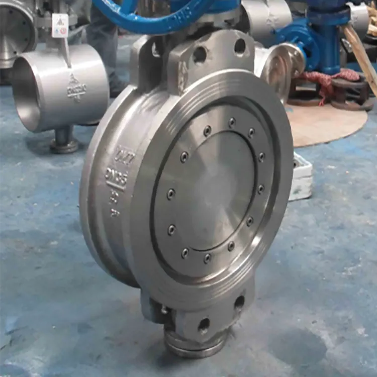
Used in occasions where quick opening and closing or low resistance is required; used in high-pressure pipelines and pipelines with low pressure drop; it has a long service life and is labor-saving to open and close. Suitable for occasions with larger diameters and higher pressures. Since throttling may cause damage to the seal or ball, ball valve throttling is generally not used. Full-channel ball valves are not suitable for regulating flow. Working principle of butterfly valve: The butterfly valve is composed of a valve body, a disc, a valve stem and a handle.
In many occasions, the butterfly valve replaces the stop valve and the regulating valve of the automatic control system, especially in large flow regulation occasions. It can be widely used to transport various media with an operating pressure of 2.0Mpa and an operating temperature below 200℃. Intercept and regulate flow on pipelines of water, oil, gas, liquid, slurry, and suspension. Cryogenic valve: Cryogenic valves are mainly used for valves with a medium temperature of -40℃ to -196℃. Cryogenic ball valve, cryogenic gate valve, and cryogenic stop valve. Conveying flammable, explosive, and highly permeable media, such as ethylene, liquefied natural gas, and LNG storage tanks. The medium must be gasified when heated, and the volume can expand hundreds of times when gasified. Under low temperature conditions, the tensile strength and hardness of the material increase, while the plasticity and toughness decrease, and the material is brittle at low temperature. Unqualified materials will cause external or internal leakage of the shell and sealing surface; the comprehensive mechanical properties, strength and rigidity of the parts cannot meet the use requirements or even break. This will cause the medium to leak and cause an explosion. Basic requirements: All low-temperature material parts must be cryogenically treated before finishing to reduce the shrinkage and deformation of low-temperature valves under low-temperature conditions. Valve body, valve cover, valve seat, opening and closing parts: ferritic stainless steel is used when the temperature is higher than -100℃, and austenitic stainless steel is used when the temperature is lower than -100℃. Valve stem: Made of austenitic stainless acid-resistant steel, heat-treated to increase tensile strength, hard chrome plated (coating thickness 0.04~0.06mm), or nitrided to increase surface hardness. Fasteners: When the temperature is higher than -100℃, the bolts are made of alloy steel such as Ni, Cr-Mo, and heat-treated to prevent thread bite; when the temperature is lower than -100℃, the bolt material is austenitic stainless steel. The nut material is Mo steel or Ni steel. Gasket: When the operating temperature is higher than -196℃ and the maximum operating pressure at low temperature is 5MPa, use stainless steel with asbestos wound gasket, stainless steel with polytetrafluoroethylene wound gasket or stainless steel with expanded graphite wound gasket.
General provisions for valve installation:
Valves should be set according to the type and quantity shown on the pipeline and instrument flow diagram (PID). When PID has specific requirements for the installation position of certain valves, they should be set according to the process requirements. The type and temperature and pressure level of the valve should be selected according to the piping material level specified in each project. For valves that do not need to be operated frequently (only used when starting and stopping), if they cannot be operated on the ground, they should also be arranged in a place where a temporary ladder can be set up. The height of the center of the valve handwheel from the operating surface is between 750 and 1500mm, and the optimal height is 1200mm. The installation height of valves that do not need to be operated frequently can reach 1500-1800mm. When the installation height cannot be reduced and frequent operation is required, the design should consider setting up operating steps. The installation height and distance of valves in different directions are detailed in the figure below.
425013.webp)
When the height of the valve handwheel center from the operating surface exceeds 1800mm, a sprocket hook should be installed, and the chain of the sprocket should be about 800mm from the ground. In order not to affect the operation of the sprocket, hang the lower end of the chain on a nearby wall or pillar. For valves installed in the trench, when the trench cover can be opened to operate, the handwheel of the valve should not be lower than 300mm below the trench cover. When it is lower than 300mm, a valve extension rod should be installed to make its handwheel within 100mm below the trench cover. For valves installed in the trench that need to be operated on the ground, or valves installed under the upper floor (platform), a valve extension rod can be installed to extend the valve to the trench cover, floor, or platform for operation. The handwheel of the extension rod should be about 1200mm from the operating surface. Valves less than or equal to DN40 and threaded connections should not be operated using sprockets or extension rods to avoid damage to the valve. Under normal circumstances, extension rods and sprockets should be used as little as possible to operate valves. The distance between the handwheel of the valve arranged around the platform and the edge of the platform should not be greater than 450mm. When the valve stem and handwheel extend into the upper part of the platform and the height is less than 2000mm, it should not affect the operation and passage of the operator to avoid personal injury. When the valves are arranged adjacent to each other, the net distance between the handwheels should not be less than 100mm. Except for valves used for sedimentation materials or solid discharge due to process needs, the handwheel of general valves shall not be downward, especially the handwheel of valves on dangerous medium pipelines is strictly prohibited to face downward, so as to avoid leakage during operation and endanger personal safety. The orientation of the valve handwheel is: vertical upward, horizontal, vertical upward and tilted 45° to the left and right, vertical downward and tilted 45° to the left and right (preferably not).
953144.webp)
Valves on the bottom pipelines of equipment such as towers, reactors, and vertical containers shall not be arranged in skirts. Valves drawn together with equipment nozzles on the process piping and instrument flow diagram (P&ID) should be directly connected to the equipment nozzles. Under normal circumstances, valves used to cut off equipment should be directly connected to the equipment nozzles when conditions permit, or as close to the equipment as possible. The valve on the pipeline connected to the equipment containing highly toxic media should be directly connected to the equipment nozzle, and the valve shall not be operated by a sprocket. When designing the valve directly connected to the equipment nozzle, special attention should be paid to the flange on the valve side, which must be matched with the flange on the equipment nozzle. When the valve is a concave flange, the equipment professional should be asked to configure a convex flange on the corresponding nozzle. When the branch pipe is drawn from the main pipe, its shut-off valve should be as close to the main pipe as possible and installed at the highest point of the horizontal section of the branch pipe so that the fluid can be drained to both sides of the valve. The branch pipe shut-off valve on the pipe gallery is not frequently operated (only used when parking for maintenance). If there is no permanent ladder, the design should consider leaving space for the use of a temporary ladder. The operation of large valves should use a gear transmission mechanism, and the space required for the gear transmission mechanism should be considered during installation. Generally, valves with a gear transmission mechanism should be considered for valves larger than the following grades.
Precautions for valve operation and use
The valve opening should not be too large to prevent the valve stem from falling off the valve core. During operation, when the valve is opened to the maximum, the hand wheel should be closed 2 to 3 turns to avoid false buckling. The gate valve cannot be used as a throttle valve. During use, its opening should not be too small to reduce the scouring and corrosion of the valve core by the flowing medium. When closing the valve, it is not advisable to use too much force to avoid damage to the valve stem copper sleeve or difficulty in opening and closing. When closing the valve with a valve lever, it is not advisable to use excessive force or operate it rudely. The standard is that the valve does not leak internally. For the manual valve of the pressure gauge (especially the manual valve at high temperature or dangerous media), its opening should not be too large to avoid the valve closing time being too long when there is a large amount of leakage in the pressure gauge, which will further expand the situation. Its opening is based on the normal display pressure of the pressure gauge. The one-way valve is divided into vertical installation, flat installation and direction. Pay attention to the difference when using and installing.


939.webp)

294.webp)
476.webp)
420.webp)
146.webp)
460.webp)
287.webp)
274.webp)
688.webp)


