1. Overview of comprehensive inspection of PE gas pipelines
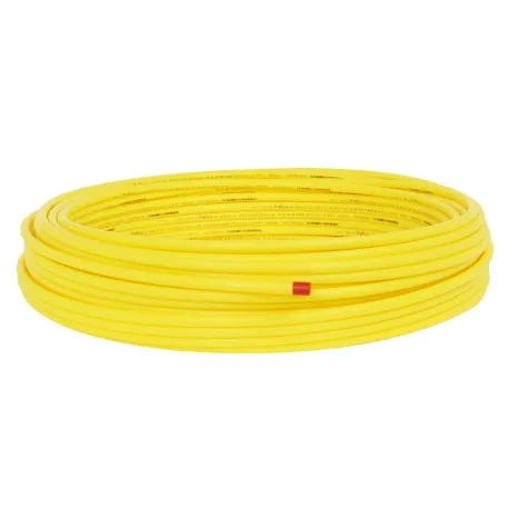
At present, PE pipelines are widely used in the construction of urban buried gas pipelines. Gas pipelines with working pressure ≤0.8MPa can use polyethylene pipelines. According to the Special Equipment Safety Law, in-use pressure pipelines must be comprehensively inspected. Comprehensive inspection of urban PE gas pipelines can be implemented according to TSG D7004-2010 "Rules for Periodic Inspection of Pressure Pipelines-Public Pipelines", but it only makes general provisions. Some regions have issued operational local standards based on local actual conditions. According to the relevant provisions of Shanghai local standard DB31/T 1162-2019 "Technical Rules for Periodic Inspection of Gas Polyethylene Pipelines", in addition to the common inspection difficulties, there are also the following unique technical difficulties for the comprehensive inspection of PE gas pipelines:
1.1 Difficulty in leak detection
Since the leaked gas will flow upward along the loose soil structure, it may spread to nearby ditches, cellars, and underground buildings (structures). Therefore, it is quite difficult to accurately locate the leak point when detecting a leak in a certain area, which is not the actual gas leak.
1.2 Difficulty in positioning and detection
Due to the design and installation without tracer devices or route markings for the pipeline, the PE gas pipeline needs to be tracked and located again during the pipeline inspection process. In addition, due to the nature of the PE pipeline insulation, it is not possible to directly apply signals to locate and detect the buried depth.
1.3 Failure mechanism is unknown
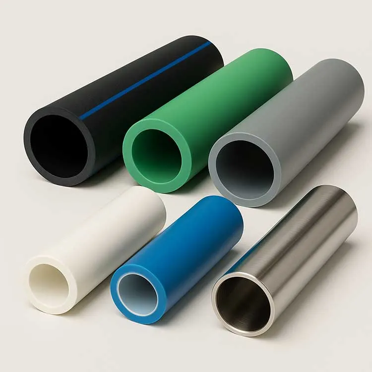
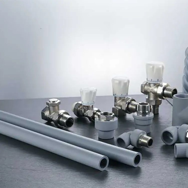
Although PE gas pipes have superior properties such as light weight, easy welding, strong corrosion resistance, long pipe service life, good flexibility, and low friction resistance, PE gas pipes, pipe fittings, valves, flanges, etc. can be composed of fully compliant units according to relevant standards, but PE gas pipes have not been used for a long time, and it is difficult to ensure that they can be effectively controlled during transportation, construction, installation and post-management. Usually, these unfavorable factors will also cause adverse effects on the entire PE gas pipeline system.
2. Comprehensive inspection requirements
According to the unique properties of PE gas pipelines and the characteristics of comprehensive inspection, the comprehensive inspection items of PE gas pipelines mainly include data review, macro inspection, direct excavation inspection, and risk assessment.
2.1 Data review
Comprehensive inspection generally requires the collection of the following data analysis: safety management data, design data, completion acceptance data, pipeline operation status data, regular inspection reports during the operation cycle, and the last comprehensive inspection report, etc.
2.2 Macro inspection
The main macro inspection items of PE gas pipelines include: ground leakage inspection, location and direction, ground mark inspection, pipeline tracer system inspection, crossing pipe section inspection, valve well inspection and inspection of other pipeline components. Among them, the surface environment survey along the pipeline mainly checks whether there is occupation, pipeline exposure, third-party construction, adverse geological environment conditions, biological invasion, etc.
2.3 Direct inspection of excavation
The main direct inspection items of excavation include: pipeline laying quality inspection (pipeline burial depth, laying quality of tracer system and warning signs, laying quality of pipe foundation, biological invasion and laying environment temperature, etc.) and pipe body condition inspection (overall quality of pipe body, measurement of wall thickness, appearance of welded joints and non-destructive testing of welding quality, etc.), and if necessary, sampling for physical and chemical performance tests such as hydrostatic strength, resistance to slow crack growth, elongation at break and oxidation induction time.
2.4 Risk assessment
The risk assessment conducts risk level assessment on PE gas pipelines based on the following data in terms of failure possibility and failure consequence. It mainly includes the investigation of design, completion, operation status and safety management data, macro inspection and direct excavation inspection data, medium characteristics, possible hazards caused by leakage, etc.
3. Technical measures taken
3.1 Pipeline detection and positioning
PE pipeline positioning technology (weak magnetic method, electromagnetic method) is usually used to detect the buried depth and direction of the pipeline. According to 6.3.4 of CJJ63-2018 "Polyethylene Gas Pipeline Engineering Technical Standard", the laying and setting of tracer wires, warning tapes, ground signs, and protective plates shall comply with the following provisions: The tracer wire shall be laid directly above the polyethylene gas pipeline and shall have good conductivity and effective electrical connection. A signal source well shall be set on the tracer wire. Usually, the tracer wire is laid close to the pipeline. The tracer wire should have metal conductivity and external insulation, and it needs to have a certain strength. The valve well should be fully utilized to set the signal source well, and the test line should be reserved. Pipeline positioning using the tracer method is shown in Figure 1.
745840.webp "pe-gas-pipe (2)745840.webp")
When installing PE gas pipelines, the laying of tracer devices should be carried out in accordance with relevant standards and specifications. However, due to some factors, the metal tracer line was not laid as required, or the metal tracer line was not connected or failed due to the later third-party construction, and the later detection often added many obstacles due to these unfavorable factors. Commonly used PE gas pipeline detection methods include ground penetrating radar method, electromagnetic method, weak magnetic method and sound wave method. For PE gas pipelines with laid tracer lines, the electromagnetic method is mainly used, and for PE gas pipelines without laid tracer lines, the ground penetrating radar method, sound wave method and weak magnetic method are mainly used.
Although the weak magnetic method is not as common as the ground penetrating radar in practical applications, it has been verified many times and still has a certain degree of credibility in the detection and positioning of PE gas pipelines. Of course, the PE gas pipeline detection technology is far less mature than the steel pipe detection equipment technology in instrument and equipment research, but by using a variety of instruments in combination, making rational use of the advantages of various detection methods and instruments, and taking advantage of their strengths and avoiding their weaknesses, the accuracy of PE gas pipeline positioning can be effectively improved. Figure 2 is a schematic diagram of the weak magnetic method for detecting PE gas pipelines.
447011.webp "pe-gas-pipe (3)447011.webp")
3.2 Leakage inspection
Use the combustible gas leak meter based on the medium analysis method to investigate the leakage of PE gas pipelines. According to the possible leakage sites, mainly check the leakage of pipeline components and connection joints. Focus on the geological disaster impact points, where bubbles emerge from the pipeline passing through the water surface, exposed sections of the pipeline caused by construction, gas leakage sounds, abnormally withered vegetation, and abnormal odors. If necessary, check the manholes, trenches, and underground structures where the gas may spread. Since the PE gas pipeline is laid underground, if a leak occurs, the ground drilling detection is carried out in the suspected leakage range, and the leakage point is gradually locked according to the leakage concentration. The on-site leakage detection is shown in Figure 3.
445592.webp "pe-gas-pipe (4)445592.webp")
3.3 Nondestructive testing of PE gas pipeline welded joints
3.3.1 Common types of welded joints
The main connection methods of PE gas pipes are hot melt welding and electric fusion welding. The connection of PE gas pipes is an important link to ensure the integrity of the gas pipeline structure and safe operation. The quality of the welded joints is directly related to the safety of pipeline operation.
3.3.2 Common types of welded joint defects
The main types of defects in PE pipe welded joints are: holes, fusion surface inclusions, cold welding, over-welding, resistance wire misalignment and pipe socket failure. The causes of each defect are different, and finding the root cause is very helpful for improving construction quality control. There are many causes of holes, including holes generated during the manufacture of pipes and fittings before welding; pores generated by steam due to material moisture or oil inclusions on the welding surface during welding; and cooling shrinkage holes generated after welding, as shown in Figure 4.
177989.webp "pe-gas-pipe (5)177989.webp")
The fusion surface inclusion defect is mainly caused by non-standard on-site construction, such as unscraped oxide scale, uncleaned welding surface, and contamination of electric fusion sleeves, as shown in Figure 5. Cold welding defects are caused by insufficient welding heat, such as insufficient welding time, excessive clearance between pipes and fittings, and power failure at the construction site, as shown in Figure 6.
319414.webp "pe-gas-pipe (6)319414.webp")
Over-welding, on the contrary, is a defect caused by excessive welding energy, generally caused by too long heating time, too high voltage, too tight fit between pipes and fittings, etc., as shown in Figure 7. Resistance wire misalignment usually occurs together with over-welding defects, generally caused by excessive material fluidity, as shown in Figure 8. Pipe socket failure is a man-made defect, mainly caused by improper operation of the welder, as shown in Figure 9.
937210.webp "pe-gas-pipe (1)937210.webp")
3.3.3 Phased array detection of welded joints
At present, the on-site detection technology for the quality of PE gas pipeline hot-melt welding joints is coupled focused ultrasonic detection technology, and the on-site detection technology for the quality of PE gas pipeline electric fusion welding joints generally adopts ultrasonic phased array dynamic focusing combined with B-scan imaging technology.
The phased array ultrasonic detection method of electric fusion welding joints is carried out in accordance with GB/T 29461-2012 "Ultrasonic Inspection of Polyethylene Pipe Electric Fusion Joints". After ultrasonic detection, safety assessment is carried out in accordance with GB/T 29460-2012 "Safety Assessment of Defective Polyethylene Pipe Electric Fusion Joints".
At present, the country has not issued corresponding standards and specifications for ultrasonic testing of hot-melt welded joints. The Shanghai Special Inspection Institute has taken the lead in formulating the local standard DB31/T1058-2017 "Phase-controlled Array Ultrasonic Testing of Polyethylene (PE) Pipe Welded Joints for Gas", which provides the ultrasonic testing method of hot-melt welded joints of polyethylene pipelines and the evaluation standards for voids, inclusions and unfused joints, which can provide a basis for safety assessment.
3.4 Physical and chemical performance testing of PE gas pipes and welded joints
The comprehensive inspection of PE gas pipelines is a risk-based inspection of pipelines in use. Since PE gas pipelines are buried underground for a long time, it is uncertain whether the geographical environment will cause changes in their physical and chemical properties. They should be confirmed by comprehensive inspection technical means. Physical and chemical performance testing is a technical means for the inherent safety of buried PE gas pipelines in the comprehensive inspection. The sample specimens are mainly subjected to hydrostatic strength test, slow crack growth resistance test, elongation at break test and oxidation induction time test. The comprehensive performance indicators of existing buried PE gas pipelines can be analyzed by sampling.
The hydrostatic strength test is carried out in accordance with the relevant requirements of GB/T 6111-2018 "Determination of the resistance to internal pressure of thermoplastic pipe systems for fluid transportation". The test temperature is 80°C, and the hoop stress is 4.5MPa (PE80) and 5.4MPa (PE100), which can evaluate the mechanical properties of the pipe.
When the nominal wall thickness of the pipe is greater than 5mm, the slow crack growth resistance test is carried out in accordance with the requirements of GB/T 18476-2019 "Determination of resistance to crack growth of polyolefin pipes for fluid transportation - Test method for slow crack growth (notch test)". The test temperature is 80°C, and the hoop stress is 4.0MPa (PE80) and 4.6MPa (PE100), which can test the pipeline damage time and evaluate the level.
The elongation at break test should be carried out according to GB/T 8804.3-2003 "Determination of tensile properties of thermoplastic pipes Part 3: Polyolefin pipes", GB/T 19810-2005 "Determination of tensile strength and failure mode of hot-melt butt joints of polyethylene (PE) pipes and fittings" and GB/T 19808-2005 "Tensile peel test of polyethylene electrofusion assemblies with a nominal outer diameter greater than or equal to 90 mm for plastic pipes and fittings".
The oxidation induction time test is carried out in accordance with the requirements of GB/T 19466.6-2009 "Plastics Differential Scanning Calorimetry (DSC) Part 6: Determination of oxidation induction time (isothermal OIT) and oxidation induction temperature (dynamic OIT)". The test temperature is 200℃, which can partially evaluate the anti-aging performance of the pipeline.
3.5 Risk Assessment of PE Gas Pipeline
Although the national standard for risk assessment of PE gas pipeline has not yet been formulated, some institutions have proposed risk assessment methods for failure possibility and failure consequences of PE gas pipeline based on the analysis of the failure causes of urban PE gas pipeline accidents. Referring to the principle of risk assessment, under the actual use environment conditions, the risk level of PE gas pipeline is comprehensively evaluated from the two aspects of failure possibility and failure consequences. This is a semi-quantitative risk assessment method that is fully applicable to PE gas pipeline.
The decision tree qualitative analysis method is used to determine the failure possibility score according to the weight of each factor, and the failure consequence score is determined by the hierarchical analysis method based on the comprehensive failure consequences. The final risk value is the product of failure consequence and failure possibility, and the risk level is assessed accordingly.
4. Engineering Practice
Using the above-mentioned PE gas pipeline inspection and testing method, a detailed inspection plan was formulated according to the actual characteristics of a certain project, and a comprehensive inspection was carried out. During the inspection, it was found that there were problems such as failure of the tracer system, insufficient burial depth of some pipe sections, and illegal occupation. The appearance inspection of the excavation site was qualified. In addition, the welded joints of the pipeline were sampled for phased array nondestructive testing, and the samples were subjected to hydrostatic test, tensile peel test and thermal stability test, and the test results were all qualified.
5. Conclusion
The urban PE gas pipeline with a design pressure greater than 0.1MPa is a pressure pipeline. Whether it is for safe operation considerations or the requirements of relevant laws and regulations, the in-service PE gas pipeline should be fully inspected, but the national standard system for comprehensive inspection of PE gas pipelines has not yet been issued. This paper mainly focuses on the technical difficulties and key points such as difficulty in positioning detection, difficulty in leak detection, and unclear failure mechanism, and discusses the comprehensive inspection method of PE gas pipelines based on the principles and technical means of commonly used on-site inspection and testing instruments and equipment. Whether the method is usable remains to be discussed and verified. At the same time, it is hoped that the regular inspection standards for PE gas pipelines can be issued as soon as possible, which will be conducive to more rapid and effective comprehensive inspection work and ensure the safe operation of PE gas pipelines.
981.webp)
 (1)379.webp)
294.webp)
476.webp)
420.webp)
146.webp)
460.webp)
287.webp)
274.webp)
688.webp)